How to perform acoustic mapping in Kryptos?
Map acoustic (ultrasonic) gas leak detectors in Kryptos by adding an acoustic gas component, entering each detector's listening range as the grade size, and giving the mapping its own name.
5 min read
Acoustic gas leak detectors listen for the high-pitched sound of gas escaping from a pressurised leak. They do not wait for the gas to drift towards them, so they can raise the alarm before a cloud has built up. Each one hears everything within its listening range, in every direction.
Kryptos has no separate screen for acoustic mapping, and it does not need one. An acoustic detector covers a sphere around itself, which is exactly how Kryptos treats a point gas detector. So you add acoustic detection as its own gas component, give it the listening range as its size, and map it like any other gas. It gets its own risk grades, its own detectors and its own lines in the results, kept apart from your hydrocarbon or toxic gas detectors.
Step 1: Add the acoustic component
Gas components are the gases (or, here, the kind of detection) your project maps. They are set once for the whole project.
- Open the Project Settings tab, then Gas Component & Optimisation Settings.
- Click Add Component at the bottom of the table. A new row appears.
- Enter a short Component ID, such as
ACO, and a Component Name, such asAcoustic. The ID is what you see in the area settings and the tree. - Make sure Enabled is ticked for the new row.
- Untick OPGD Available?. Acoustic detectors sit at one spot and listen around them, so there is no open path beam to place. The OPGD heights grey out.
- Set the PGD Start Height and PGD End Height: how far above a deck the optimiser may mount the detectors. We kept 0.5 m to 1.5 m.
- Click Apply Changes.
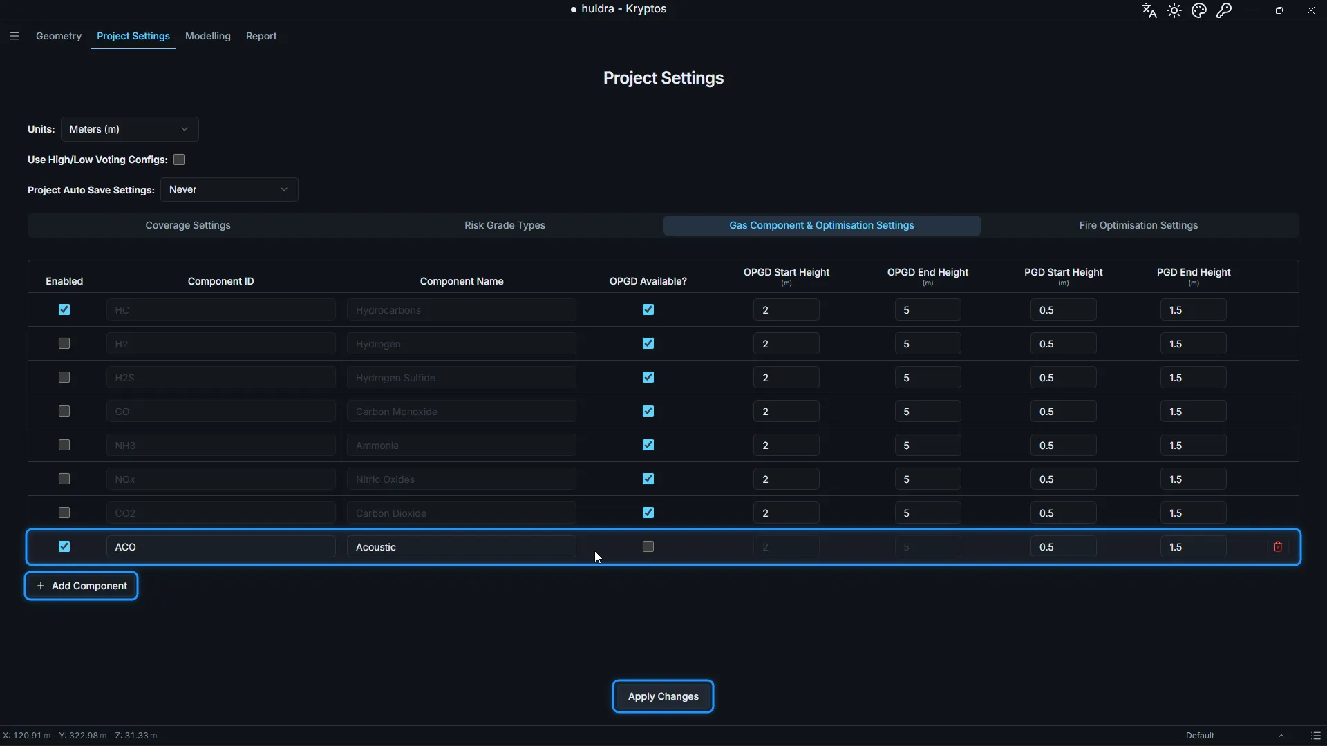
Once the component exists, every area in the project can use it. For everything else on this tab, see Gas Component & Optimisation Settings in the Kryptos documentation.
Step 2: Enter the listening range in the area
- Open the area and click Area Settings in the ribbon.
- Under Gas Mapping Parameters, tick Enabled for the
ACOrow. - In each risk grade column, enter twice the detector’s listening range. For a normal gas, this box is the size of the gas cloud, measured across. A detector that hears a leak up to 7.5 m away covers a sphere 15 m across, so it gets 15.
- Click Apply Changes.
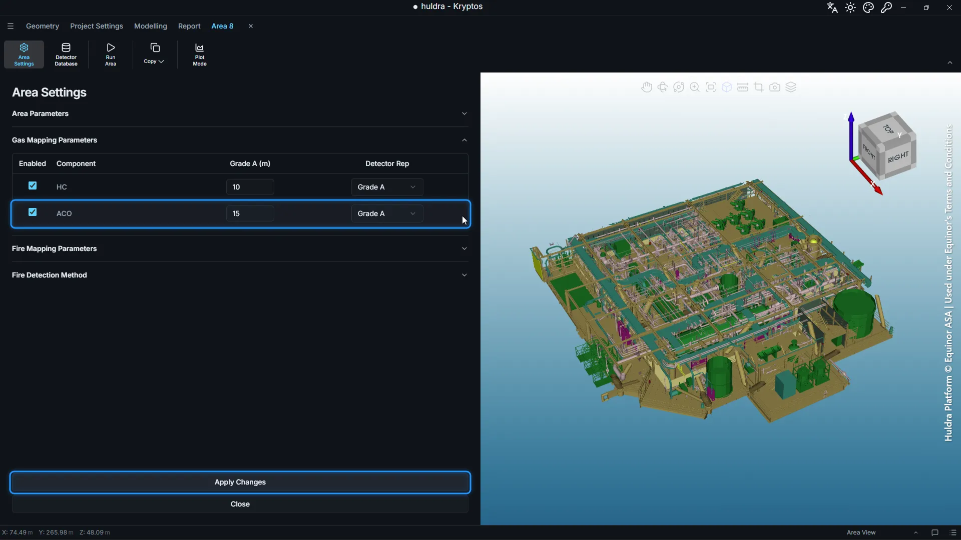
Kryptos only creates the mapping when you apply the changes. A new item, Gas Mapping for ACO, appears in the area tree, with its own Risk Grade and Configurations, next to your other gas and fire mappings.
Where the range comes from
Take the listening range from the detector supplier’s data for the background noise in that area. Pumps, compressors and control valves make their own high-pitched noise, and the detector has to hear the leak over it. A quiet area lets a detector hear much further than a loud one. So:
- Use a smaller range in noisy areas, such as compressor modules, and a larger one in quiet areas.
- Different areas can have different ranges. Each area keeps its own values in Area Settings.
- Different grades can have different ranges too, if your Fire & Gas philosophy asks for a smaller leak to be heard in higher risk areas.
Step 3: Rename the mapping
“Gas Mapping for ACO” is accurate, but it is not what you will want in the report. Give the mapping a name everyone will recognise.
- Double-click Gas Mapping for ACO in the area tree, or select it and press F2.
- Type the new name, such as
Acoustic Mapping, and press Enter.
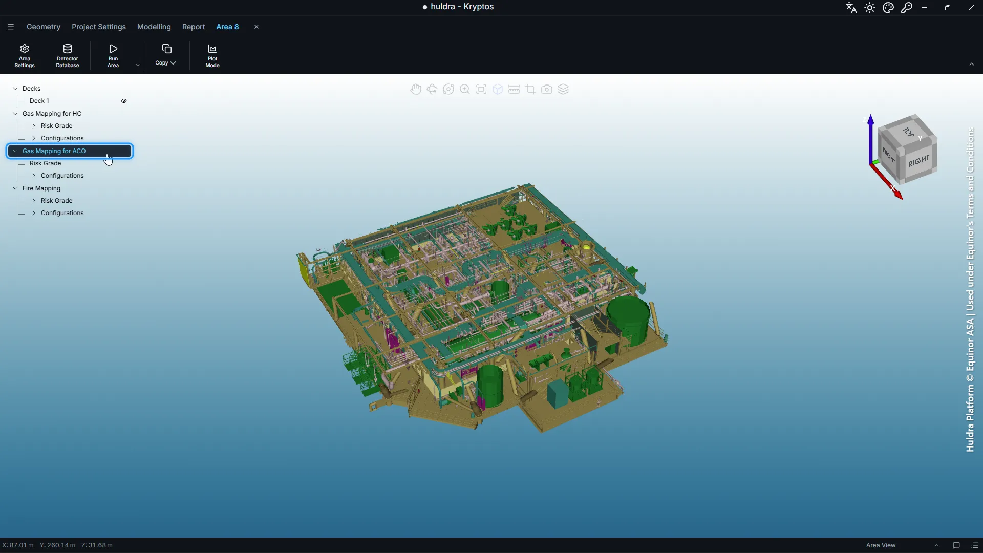
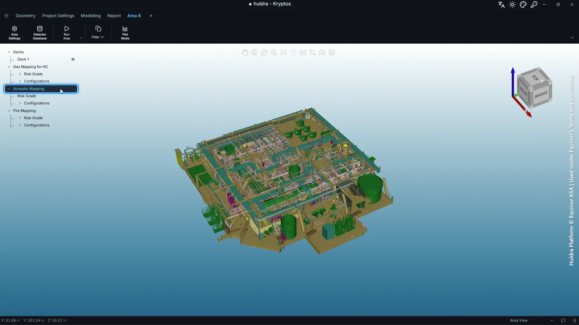
The new name is used everywhere the mapping appears: the tree, the summary, the Excel export and the report.
Step 4: Grades, decks and detectors
From here, acoustic mapping works like any other gas mapping.
- Draw the risk grades under Acoustic Mapping around the pressurised equipment you want covered: select Risk Grade, click Add Grade, draw the volume and click Complete. If you have not drawn a grade before, the Risk Grades section of the Kryptos documentation walks through every shape and setting.
- Draw the decks where detectors may be mounted, if the area does not have them already. Decks are shared by every mapping in the area.
- Set the target coverage for each grade in Project Settings → Risk Grade Types.
- Click Run Area, add an empty configuration under Acoustic Mapping and click Start Optimisation. Or place the detectors yourself with Add in the ribbon.
The full walk-through, with every step timed on a real deck, is in Gas detectors auto-placed by Kryptos on a real offshore deck, in 1 minute 8 seconds.
Tips
- Keep acoustic results apart. Each gas component has its own mapping, its own configurations and its own rows in the summary and report. Your acoustic coverage never mixes with your hydrocarbon detector coverage.
- Lock what is already there. If some acoustic detectors must stay where they are, place them first and lock them. Kryptos counts what they cover and only adds detectors where coverage falls short.
- Check the ranges before you report. Acoustic coverage depends on the leak’s pressure and the noise around it as much as on the detector. Confirm the ranges with the detector supplier for your plant’s conditions.
Credits and acknowledgements
The plant model in this post is the Huldra platform, © Equinor ASA, used under Equinor’s Terms and Conditions. Our thanks to Equinor for making the Huldra data openly available, which lets us show Kryptos working on a real offshore platform.
Every screenshot that shows the model carries this credit. Equinor has not reviewed or endorsed this post or Kryptos.
Model credit: Huldra Platform © Equinor ASA | Used under Equinor's Terms and Conditions